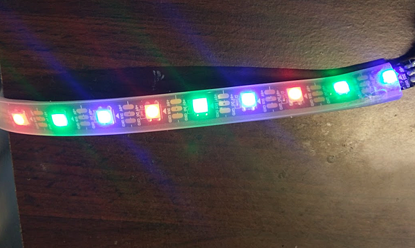
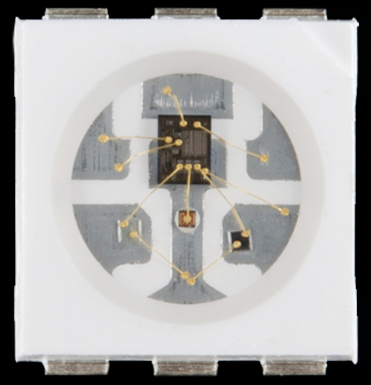
WS2812 RGB LED是具有內建驅動晶片功能的LED, 亦是使用5050 LED封裝加入驅動晶片, 驅動方式採串列進出, 因此可獨立控制串接LEDs的每一顆LED.
每個一R/G/B顏色可獨立控制,且每一個顏色可調整0~255階調,因此每一個顏色需用到8bit控制,每一顆LED需用到24bit控制.
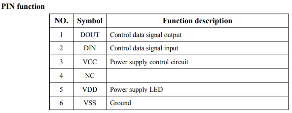
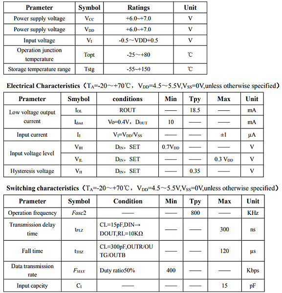
VDD電壓為6.0V~7.0V, 但實際操作使用5V可正常驅動.
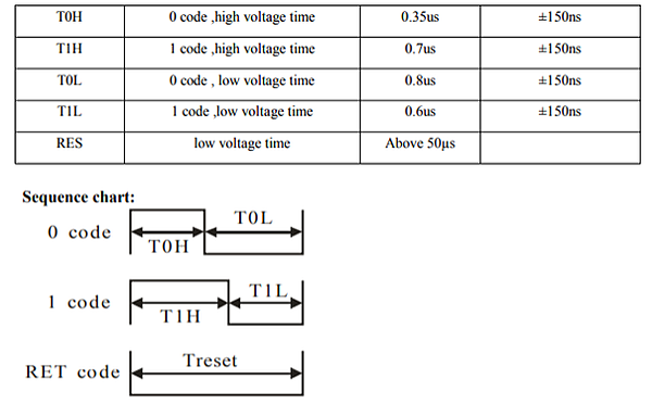
操作時序
1個Colck週期的0或1的正負周期有規範
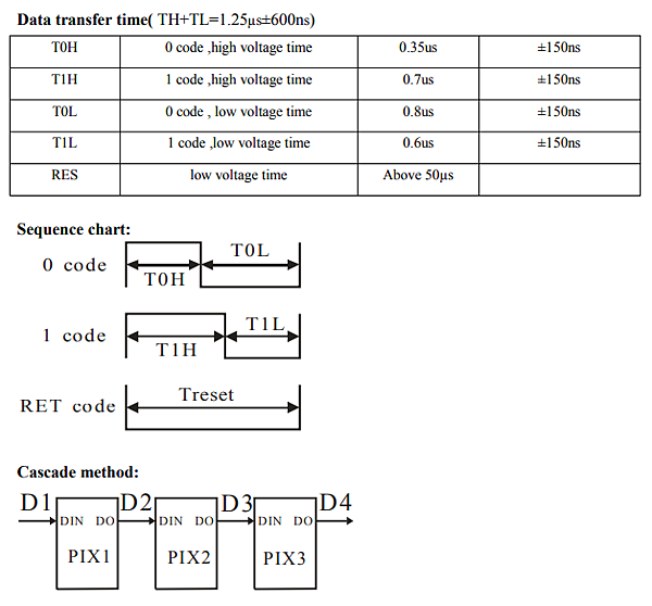
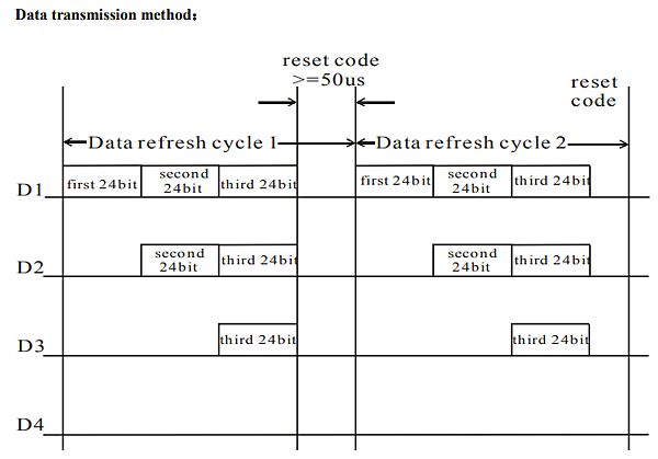
由於是採串列控制,因此每個LED需使用24bit控制,整串LED的data傳送完再執行Rest code.
另外,這個LED晶片具有保持功能, 當電源未斷電的狀態下, 如果沒有提供輸入訊號, LED燈會保持在最後控制當下.
所以在控制時,有時需做清除的動作,才不會殘留上一次操作的顏色.
1.硬體操作
控制板:Arduino UNO
材料: WS2812 LED
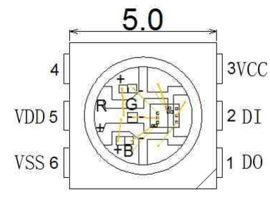
2.I/O規劃與Library
(1) 1個輸出控制腳位,作為控制LED。
(2) Arduino example: light_ws2812
3.程式
light_ws2812 example Blinky
#include

WS2812 LED(1); // 1 LED
cRGB value;
void setup() {
	LED.setOutput(9); // Digital Pin 9
}

void loop() {
	value.b = 255; value.g = 0; value.r = 0; // 設定RGB顏色 0-255
	LED.set_crgb_at(0, value); // 設定第1顆LED的RGB顏色,這個範例只能控制第1顆.
	LED.sync(); // 輸出資料至LED
	delay(500); // Wait 500 ms

	value.b = 0; value.g = 0; value.r = 255; // RGB Value -> Red
	LED.set_crgb_at(0, value); // Set value at LED found at index 0
	LED.sync(); // Sends the value to the LED
	delay(500); // Wait 500 ms
}
light_ws2812 example fade_rgb
#include

#define outputPin 7  // Digital output pin (default: 7) 設定輸出至LED燈串的腳位
#define LEDCount 9   // Number of LEDs to drive (default: 9) LED控制數量


WS2812 LED(LEDCount);
cRGB value;

byte intensity;
byte sign;

void setup() {
	LED.setOutput(outputPin); // Digital Pin 7

    //這裡是設定RGB排列方式
	//LED.setColorOrderRGB();  // Uncomment for RGB color order
	//LED.setColorOrderBRG();  // Uncomment for BRG color order
	//LED.setColorOrderGRB();  // Uncomment for GRB color order (Default; will be used if none other is defined.)

	intensity = 0; //階調
	sign = 1;
}

//0-255階調變化
void loop() {
	int i = 0;
	if (sign) {
		intensity++;
		if (intensity == 255)
			sign = 0;
	}
	else {
		intensity--;
		if (intensity == 0)
			sign = 1;
	}

    //3顆LED分別顯示R/G/B依此循環整串LED
	while (i < LEDCount){
		if ((i % 3) == 0) {  // First LED, and every third after that
			value.b = 0;
			value.g = 0;
			value.r = intensity; // RGB Value -> Red Only
			LED.set_crgb_at(i, value); // Set value at LED found at index 0
		}
		else if ((i % 3) == 1) { // Second LED, and every third after that
			value.b = 0;
			value.g = intensity;
			value.r = 0; // RGB Value -> Green Only
			LED.set_crgb_at(i, value); // Set value at LED found at index 0
		}
		else  { // Third LED, and every third after that
			value.b = intensity;
			value.g = 0;
			value.r = 0; // RGB Value -> Blue Only
			LED.set_crgb_at(i, value); // Set value at LED found at index 0
		}
		i++;
	}

	LED.sync(); // Sends the data to the LEDs
	delay(10); // Wait (ms)
}
=主程式簡化=
void loop() {
	int i = 0;
	if (sign) {
		intensity++;
		if (intensity == 255)
			sign = 0;
	}
	else {
		intensity--;
		if (intensity == 0)
			sign = 1;
	}

    //3顆LED分別顯示R/G/B依此循環整串LED
	while (i < LEDCount){
		    value.r = intensity*((i%3)%2);
         value.b = intensity*(((i+1)%3)%2);
         value.g = intensity*(((i+2)%3)%2);
			LED.set_crgb_at(i, value);
		i++;
	}
	LED.sync(); // Sends the data to the LEDs
	delay(10); // Wait (ms)
}
時序分析
從時序規則來看, 上升緣為觸發條件.
0 code的正週期較窄(0.35us)負週期較寬(0.8us).
1 code的正週期較寬(0.7us)負週期較寬(0.6us).
設R=170(0b10101010) G=0 B=0

設R=0 G=170(0b10101010) B=0
![]()
析設R=0 G=0 B=170(0b10101010)

因此這組LED採GRB控制順序
Uncomment for GRB color order (Default; will be used if none other is defined.)
Bit 1 正880ns 負430ns (1.31us)
Bit 0 正320ns 負1000ns (1.32us)

 留言列表
留言列表
